When the plumber has completed the foundation plumbing ‘ground’, the home is ready for foundation make-up. The material for this work consists of 6 mil. Black polyethylene, several rolls of plastic tape and black plastic roofing cement or ‘mastic’ – not oil!
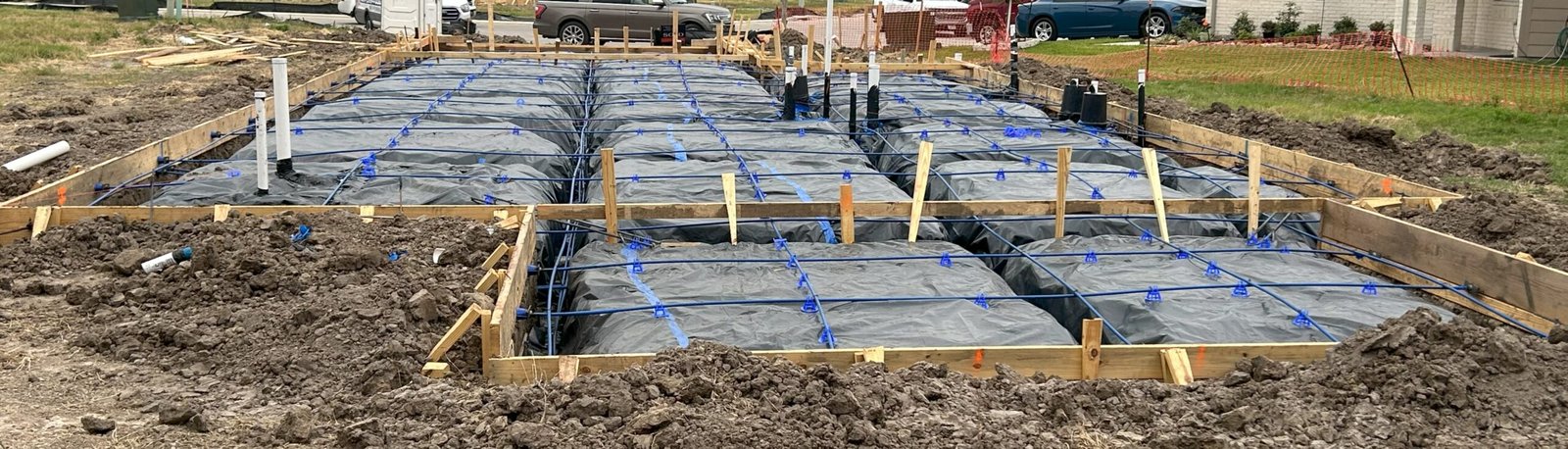
The foundation make-up crew digs out the foundation beams according to the foundation plan. Grades the sand to provide the desired thickness of slab and installs the vapor barrier consisting of 6 mil polyethylene. He seals all slab penetrations with tape and plastic cement known as “Black Mastic”.
If the plumber has not dug a drainage trench, the make-up crew will dig a trench from the slab to the street to
provide drainage. This protects the make-up contractor’s work from major damage from rain and standing water.
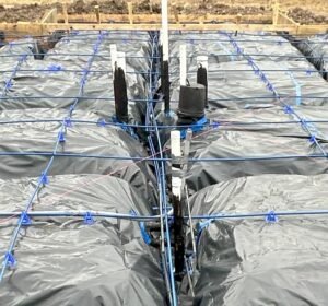
When all beams have been dug, the grade is correct and the poly has been completely installed, the make-up contractor installs cable “tendons” and supports them according to the engineering layout. Rebar “chairs” support the tendons on top of the “pads” and away from any pipes or other obstructions and uses “S-hooks” to support tendons that are supported by other tendons.
The makeup contractor installs any needed rebar dowels at re-entrant (inside) corners or added reinforcing steel at areas that the engineering shows require added support. If indicated, special corner bars should be made and installed per the engineering to form a continuous rebar reinforcement.
Occasionally, even though the design uses tendons for primary reinforcement, an engineer may call for either welded wire mesh or a rebar “mat” may be specified to be constructed using rebar rods in a checkerboard pattern. If included, the wire mesh or rebar mats are wired together and supported by rebar ‘chairs’ to hold them in the center of the concrete.
Note that some engineers will have special requirements such as void boxes, etc. that are intended to allow the soil to expand upwards without impacting (cracking) the floor of your foundation.
Items that you should check:
- Address is Posted
- Wrap Slab the Same Day
- Do not allow a ‘made-up’ slab to sit overnight without being wrapped with poly.
- Damage can occur from weather, vandalism, playing children, etc.
- Confirm Plumbing was Not Damaged
- Check with the make-up contractor as to whether his crew may have damaged any underground piping when digging the beams. If there is ANY damage, DO NOT POUR the slab until it has been corrected.
- Trench Dug for Beam Drainage.
- Trench should be lower than the foundation beams and run to the street to prevent the beams from holding water.
- Check Slab Thickness,
- Check with your engineer to confirm your desired slab thickness. Generally
engineers design slabs to be from 3-1/2″ to 4-1/2″ thick plus the depth of the foundation
beams. Run a string line across the form from one side to the other. Measure
down from the string with a tape measure. - Note that when you place your concrete, the weight of the concrete will tend to
compact your foundation sand – up to 1/2″. For this reason, your grade on your
foundation ‘pads’ must be extremely ‘tight’. A difference of 1/2″ on a 3000
Square Foot slab will add over 4-1/2 cubic yards of concrete. That amounts to
over $600.00 or more!
- Check with your engineer to confirm your desired slab thickness. Generally
- Check Beams – Location, Depth, and Width
- Confirm that the beam locations, depth, and width correspond to the plans.
- Confirm the size of the beams using your foundation engineering.
- Note that beams should be ‘centered’ under walls. Many make-up crews do not center
their beams under walls and this could be a structural issue.
 Stub-Outs are Sealed
- Plumbing and other slab penetrations need to be sealed with mastic and / or duct tape.
- Poly Splices are Taped
- All seams in the Poly vapor barrier should be taped.
- There should be no holes in the poly.
- Poly Follows Beam Contours
- Poly must follow the beam contours and rest on the bottom of the beam.
- Poly Covers the Bottom of Exterior Beams
- Poly must cover the bottom of the beams at exterior walls.
- Check Raised or Dropped Areas
- At raised or dropped areas, sand should be dropped. Allow for slope of 12 inches out for each inch of drop. i.e.: a 4″ drop in slab elevation must be sloped 4′ from the drop.
- Check Pipes Crossing Beams
-
- Poly should run under pipes crossing beams.
- There should be 4″ of concrete under all pipes crossing beams.
- Where a pipe crosses a beam, it should have a larger pipe “sleeved” around it so that foundation movement will not cause the pipe to fail or break.
-
- Check Wing walls and Column Footings
- Maintain beam depth in wing walls and column footings.
- Check Dropped Areas
- Confirm that sand graded at raised or dropped areas will allow for the proper depth of concrete under ‘float’ forms. Float lumber dimensions are usually 3-1/2″ to 5-1/2″.
- No Lumps or Holes in Sand/Fill Under Poly
- Slab ‘pads’ should be even and contain no lumps or foreign material.
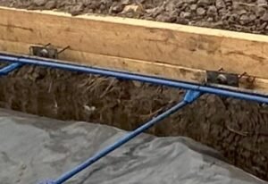
- The “Live End” of the Tendons are Secured on the Outside of the Foundation Forms using “Cathead” Clamps and are Tightened Appropriately.
- Each tendon has a “Live End” and a Dead End. The Dead end is permanently embedded in the foundation while the “Live End” will protrude through the foundation forms to be stressed after the foundation has had time to cure for a number of days.
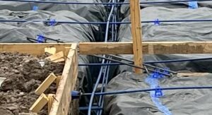
 Both the “Live Ends” and the “Dead Ends” of Foundation Tendons (cables) must be Secured Inside of the Foundation Forms with 20p (20 penny) 4″ Long Nails
- Often, when the Makeup Contractor runs out of 20p nails, they will attempt to use 16p (3-1/2″) nails. These are too short and too narrow. They will not allow the proper amount of concrete to be placed between the end of the tendon end and the foundation form. Ultimately, short nails will fail to support the tendon ends and become dislodged when the concrete is placed, resulting in foundation reinforcement problems.
- Foundation Tendons (cables) are Placed According to the Foundation Engineering / Design
- Tendons are typically 4′ to 6″ apart depending on the Foundation Engineering / Design.
- Dropped Tendons in Beams are supported Evenly and Have the Appropriate Rise at the Ends
- Often, engineers will require 2 tendons to be placed in certain beams.
- Foundation Tendons are Supported Throughout using Plastic “Rebar Chairs” at an Effective Spacing
- Typically, rebar chairs are spaced 30″ to 60″ apart.
- Foundation Tendons are Not Directly Touching any Foundation Plumbing Pipes
- Typically, where tendons must be placed near plumbing pipes, the makeup contractor will use plastic “rebar chairs” as “stand-offs” in order to ensure that there is enough concrete to protect the plumbing pipes once the tendons are “stressed”.
- Foundation Tendons in beams are properly supported by “S-Hooks” or “Rebar Wire Tie Pigtails” to keep them from dropping inappropriately.
 Re-Entrant Corners have Rebar Dowels if Required.
- Often, “inside” corners require added reinforcement. This is provided by appropriately dimensioned (typically 4′, 5′, or 6′ long, 1/2″ or 5/8″ [#4 or #5] rebar dowels) placed on an angle at the corner.
- See your foundation engineering for details.
- Jobsite is Clean